Quality-Diversity Optimisation
Quality-Diversity for shape optimsation of shell structures.
Research / Code
Context
Part of PrismArch research project
My Role
Computational Designer @ AKT II
For the PrismArch project the team at University of Malta developed a framework for Quality-Diversity search, which I applied to shape optimisation of shells to explore how the algorithm could be used as a design tool.
Team
Jeg Dudley, Konstantinos Sfikas
Year
2022
External Links
Algorithm & Implementation
A custom version of the MAP-Elites algorithm was implemented which takes inspiration from Feasible-Infeasible type genetic algorithms to enable MAP-Elites to do constrained optimisation. The custom algorithm is outlined below and is using two archive maps, one for feasible solutios, which are those that fullfill a displacement critera, and another for those that don't. The solutions that are not feasible will still be used to evolve new individuals with the idea that even those that don't fullfill the criteria still capture some aspect of the design space, and could still generate feasible offspring at a later stage. The algorithm is presented in detail, both in the PrismArch Deliverable , and following IASS Paper
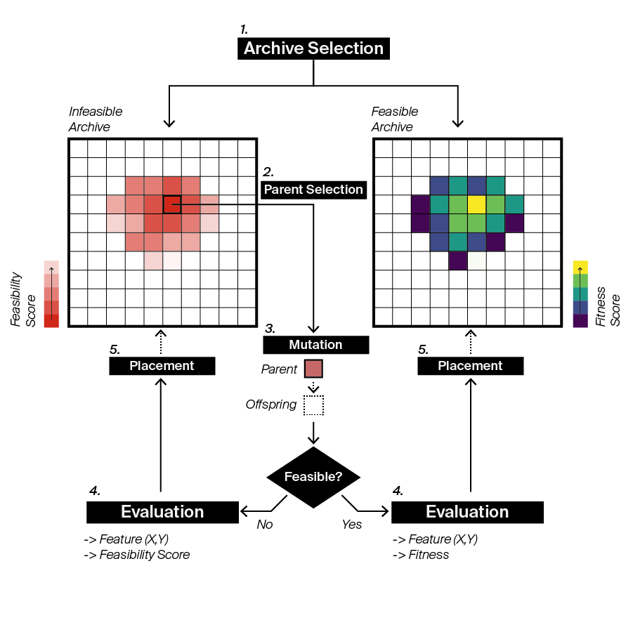
Outline of the FI-MAP-Elites algorithm developed.
The algorithm was implemented within the Grasshopper environment for Rhino as a set of components. These components allow the user to assign a base shape, as a SubD, along with point variability and boundary conditions. Feeding this along with some feature characterisations to the solver will then explore the parameterised problem and populate the feature map. The optimisation uses geometric aspects for feature categorisation and elastic energy as fitness. The elastic energy is evaluated internally using Karamba in the evolution, and the final fitness is selected as the highest internal elastic energy of all the defined loadcases.
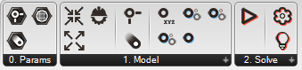
Grasshopper toolbar.
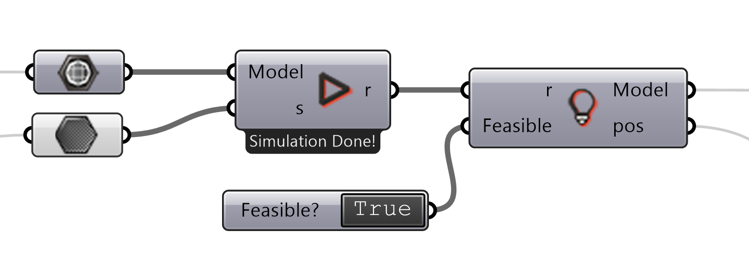
Main solver component.
Simple test case
Initial studies, to understand the general behaviour of the algorithm and how the map could be used as a design tools, were carried out on simple shell shapes. Below is an example of these with a shell supported on four points with a circular shape in plan, subject to an evenly distributed load. For this example the two features were chosen as the height of the middle bit of the shell, and the difference in height between the free spanning edges. This aims to capture two critical aspects of this, namely the general height along with the symmetry of the arches.
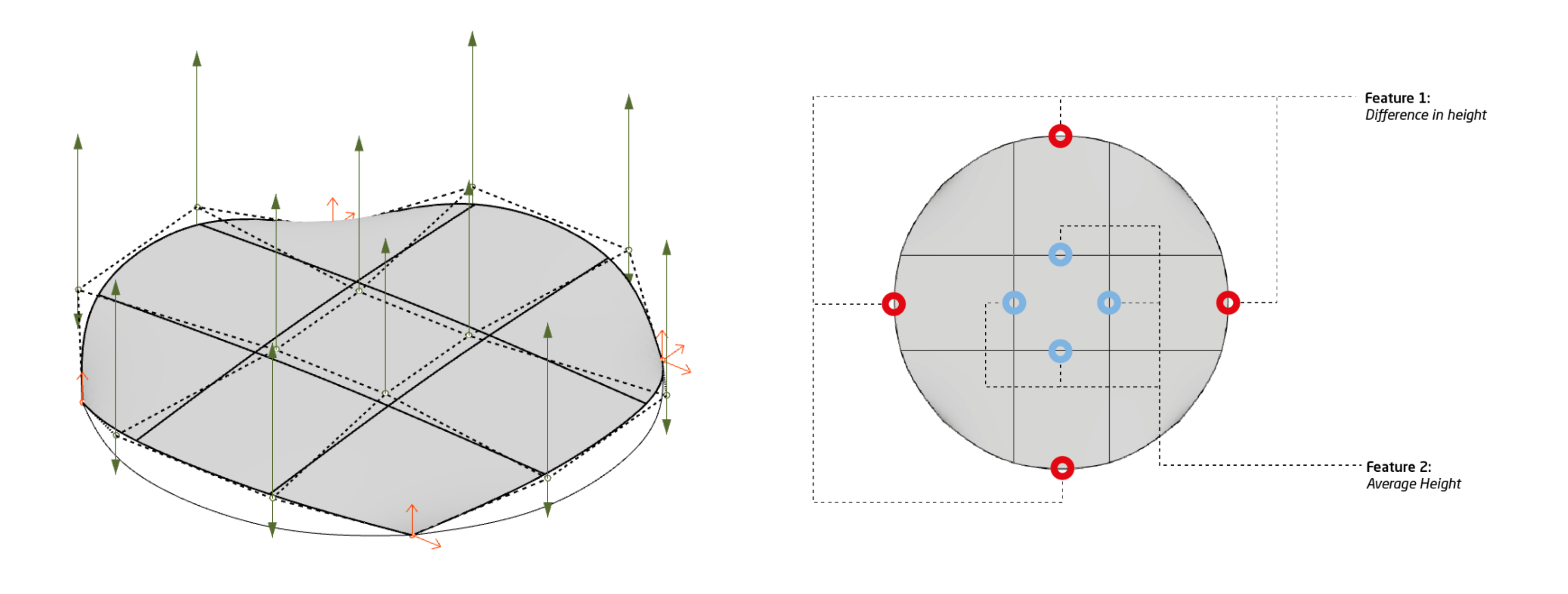
Base geometry and feature categorisation for one of the simple test cases which is a circular base shape supported on four points.
The green arrows show the potential variation in the control points and the orange arrow show the boundary conditions.
Evolution of a map for the problem above, showing the fittest individuals have a high middle and low, symmetric arches, creating a dome like shape.
Real world case study
To test the way the algorithm could be applied in a more realistic scenario, a further study was undertaken which was inspired by the shells found in the design for the Algier presidential palace, which can be seen here . This was chosen as it provides an interesting, yet regular, shell which is not perfectly form found, as it is a product of negotiation between the architect and the engineer. Further, to design this shell, engineers at AKT II used genetic algorithms to find a high performing solution [1], which positions the original design within the lineage of algorithms which the one we are exploring follows on from. This is further discussed in the IASS paper where the highest performing solutions from both processes also are compared. The parameterisation for the shell along with the behaviour categorisations is shown below.
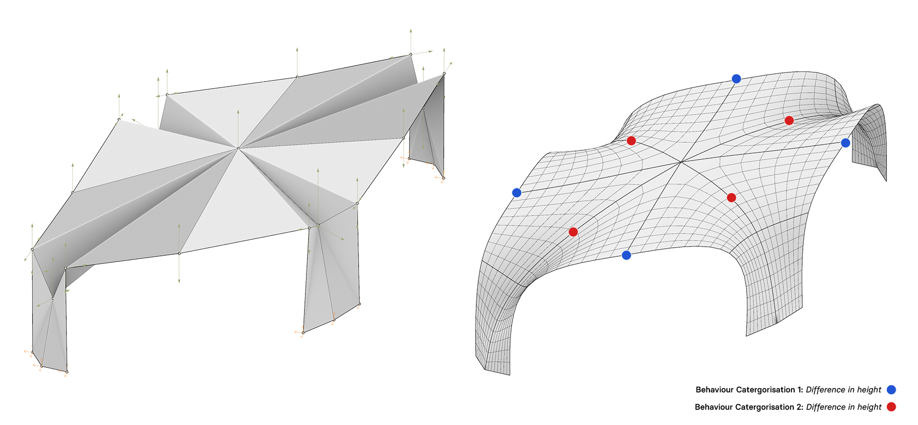
The base geometry for the shape parameterisation. Left shows the control mesh and right shows the smooth shell shape.
The green arrows show the potential variation in the control points and the orange arrow show the boundary conditions.
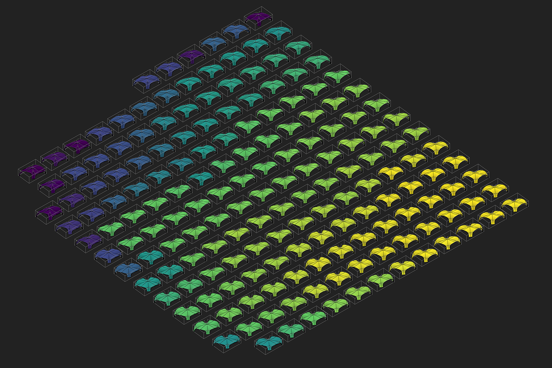
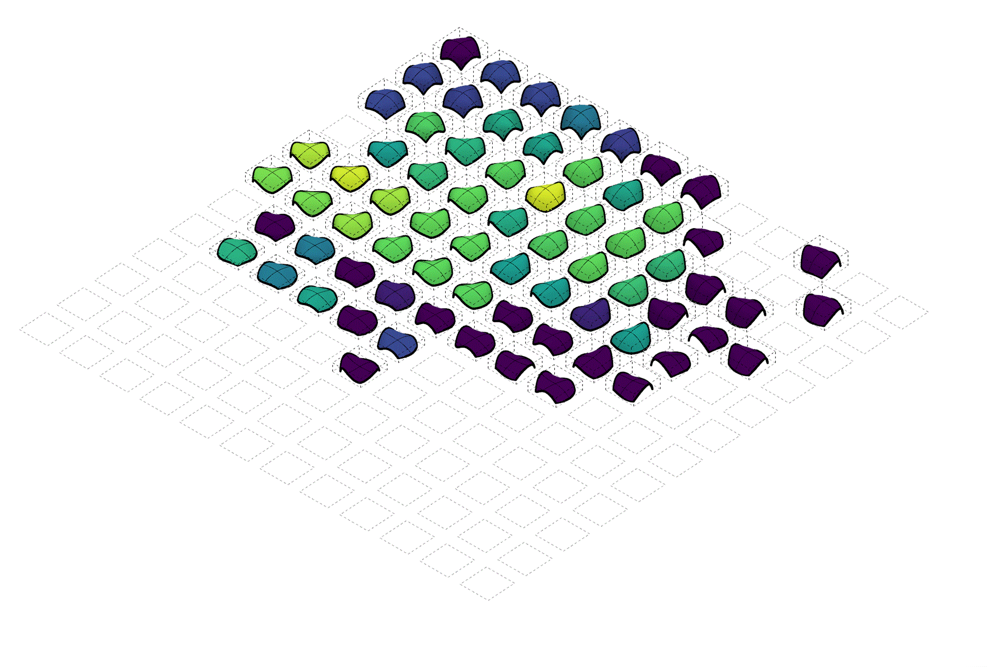
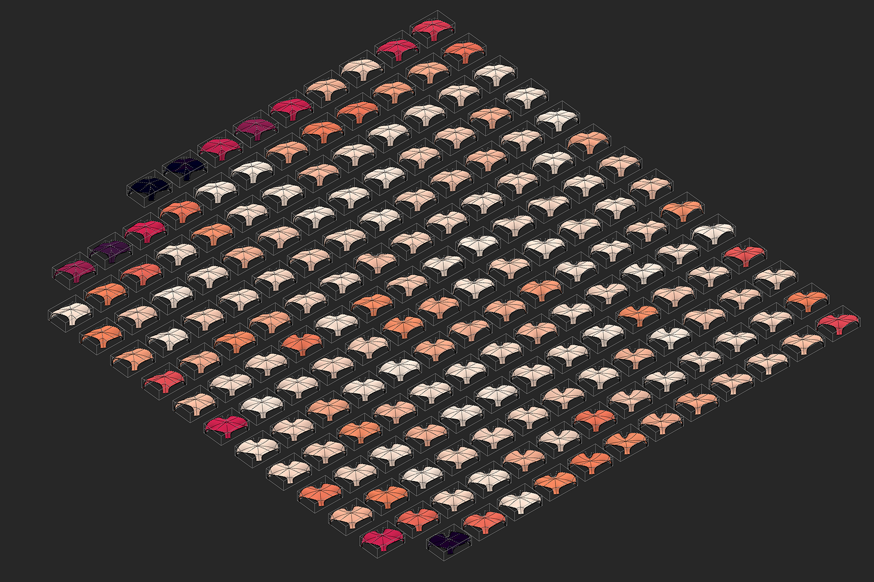
The map of feasible solutions for the Algiers Presidential Palace shell.
Yellow shows higher performing individuals.
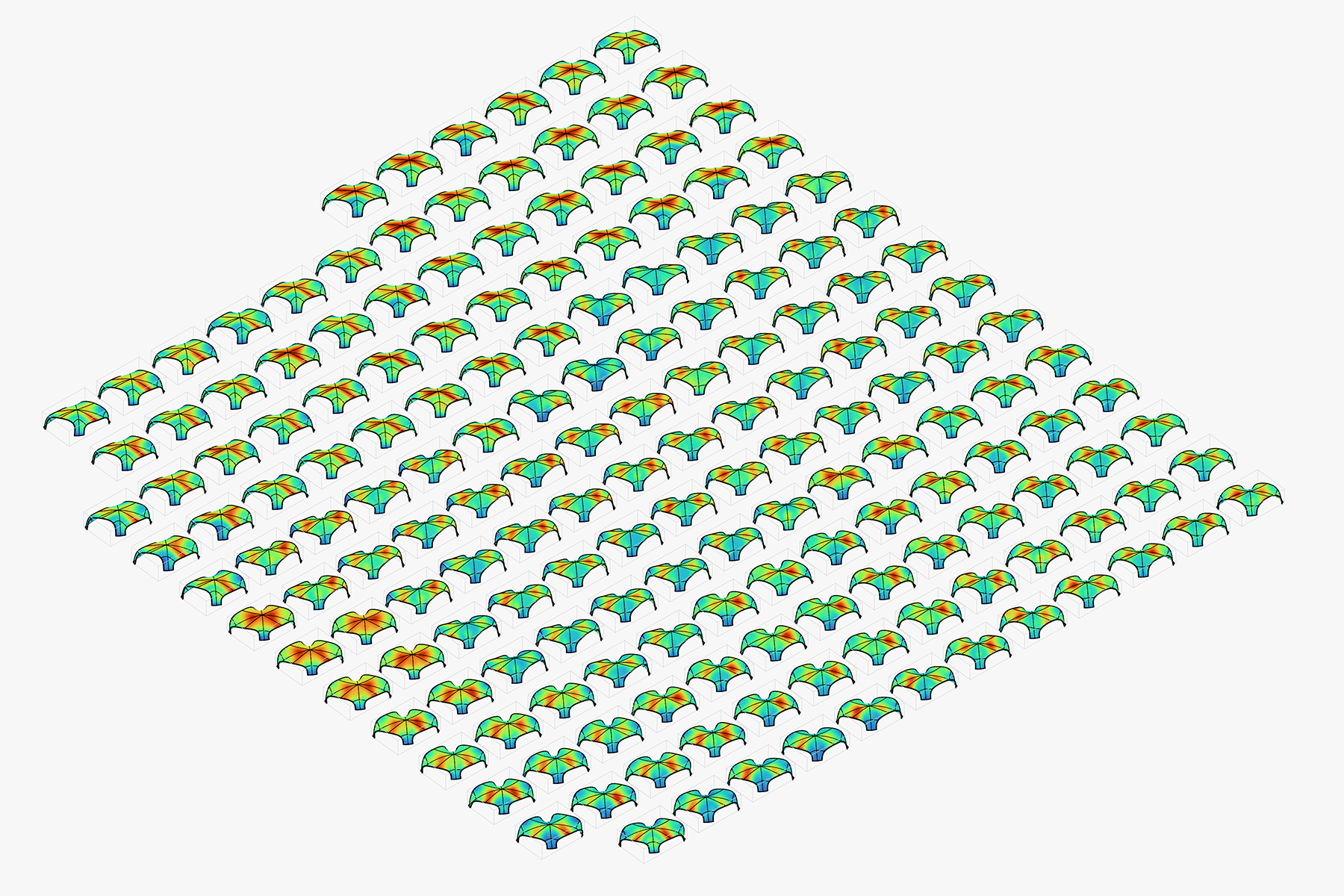
The map above with displacement plot as false colour.
Red shows the location with highest displacement relative to each shell.
The map of infeasible solutions for the Algiers Presidential Palace shell.
White shows solutions closer to being feasible.
[1] J. Janssen and R. Parker, “Hybrid Shells”, in Design Engineering Refocused, Wiley 2017, H. Kara and D. Bosia, Eds.